 English
 中文简体
中文简体Industry News
HOME / BLOG / Industry News / How to Calculate Capillary Tube Length: Bores, Exponents, and Field Checks




A service technician trims a replacement capillary 150 mm shorter than the failed original, expecting a slightly richer circuit. What actually happens is roughly five percent more refrigerant mass flow, higher suction pressure, a flooded evaporator, and almost no superheat at the compressor return. In a critically charged system there is no thermostatic expansion valve to absorb that mistake.
Capillary tube length is a dependent variable, not a starting point. Bore, refrigerant, and the mass flow the evaporator needs come first; the length is then solved for. The sections below work through that sequence, the exponents that let you rescale a tube you already have, and the checks that keep a calculated number from turning into a field failure.
Content
A capillary tube is a fixed restriction. Subcooled liquid enters at condensing pressure, flashes as pressure falls, accelerates through the bore, and in most designs reaches sonic velocity near the outlet. Once the flow is choked, the pressure downstream stops influencing mass flow. That is the self-compensating behavior that makes capillary tubes attractive: the tube passes less refrigerant automatically when condensing pressure drops.
The compensation has limits, and both dimensions share the work. Lengthen a tube by 10 percent at a fixed bore and mass flow falls by around five percent. Widen the bore by 10 percent at a fixed length and mass flow rises by more than 20 percent.
For orientation, domestic refrigerator and freezer circuits commonly run bores between roughly 0.5 mm and 1.0 mm inside diameter with coiled lengths of about 2 m to 4 m. Light commercial display cases and water coolers more often sit between 1.0 mm and 2.0 mm at 1.5 m to 3 m. Those are starting envelopes, not specifications.
Skip any one of these and the result will be wrong in a way that stays invisible until the unit is running.
Divide the capacity by the enthalpy of evaporation at the evaporating temperature. Mass flow in kilograms per second equals capacity in kilowatts divided by the enthalpy difference in kilojoules per kilogram. A 1.2 kW circuit with 165 kJ/kg of refrigerating effect needs 1200 divided by 165000, or about 0.0073 kg/s, which is 7.3 g/s.
Choked flow fixes the maximum mass flux for a given inlet state, so the required cross-section follows from the target mass flow. Work backward from a realistic flux instead of guessing a bore. If the calculation demands an unreasonable flux, the problem is usually the chosen evaporating or condensing temperature, not the tube.
The standard approach integrates momentum and energy along the tube. Subcooled liquid runs single-phase at the inlet, where a Darcy-Weisbach friction factor from a Colebrook-type correlation applies. After the flash point the flow is two-phase and the pressure gradient rises sharply, so homogeneous or separated two-phase models are used, with a delay term for the metastable liquid that survives past the saturation pressure. Published empirical correlations fitted to small hermetic systems do the same job with far less computation, provided the bore, refrigerant, and capacity fall inside their validated range.
Compare evaporating pressure with condensing pressure. For many common refrigerants the critical pressure ratio sits between about 0.4 and 0.6, depending on refrigerant and subcooling. Below that threshold, mass flow is set by the inlet state and geometry alone and the length calculation holds. Above it, the tube is not choked, evaporator pressure affects flow, and the same calculation will under-predict the required length.
When a matching original is unavailable, rescaling a known tube is the fastest route. A widely used resizing relation is L2 = L1 x (D2 / D1)^4.6, where L is length and D is inside diameter. A 3.5 m tube at 1.5 mm becomes 1.81 m at 1.3 mm.
Read that exponent backwards and it tells you something useful: length scaling with the 4.6 power of diameter implies mass flow scaling with roughly the 2.3 power, which lines up with measured choked-flow behavior in small tubes.
The length exponent is gentler. Mass flow varies approximately with the inverse square root of length, so lengthening by 20 percent reduces flow by about 9 percent, while shortening by 20 percent raises it by about 12 percent. That asymmetry decides how much material you leave on the tube before bench testing.
| Design change | Typical range | Effect on mass flow | Practical compensation |
|---|---|---|---|
| Bore, inside diameter | 0.6 mm to 2.0 mm | Rises with roughly D^2.3 | Required length scales with D^4.6 |
| Tube length | 1.5 m to 4 m coiled | Falls with roughly L^-0.5 | 20 percent more length cuts flow about 9 percent |
| Liquid subcooling | 0 K to 10 K | Roughly 1 percent per kelvin, indicative | Longer tube or revised charge |
| Condensing pressure | About 1 bar either side of design | Higher inlet pressure raises flow | Recalculate at worst-case ambient |
| Evaporating pressure when choked | Below the critical pressure ratio | Almost no effect | None, the tube is already choked |
Change the evaporator from a wire tube coil to a finned copper tube coil and the same capillary delivers a different superheat, because internal pressure drop and refrigerant distribution have changed. Coil substitutions are therefore a reason to recheck the capillary rather than assume the old length still applies.
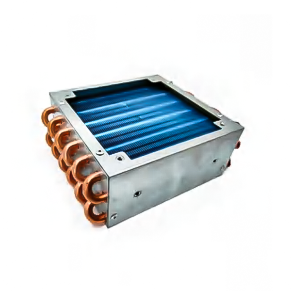 153 Fin Type Evaporator with Copper TubeCopper-tube finned evaporator with multiple tube pitch, row pitch, fin pitch, and fin type options; suited to coil replacement reviews where capillary matching is reassessed.View Product →
If you are matching bore to coil geometry rather than starting from a blank sheet, our note on fin type evaporator design and selection covers the trade-offs between aluminum and copper circuits in more detail.
A compact condenser mounted inside the cabinet behaves differently from a natural-draft wire tube condenser on the back panel. The internal unit often runs with more subcooling at the same ambient, which raises mass flow and pushes the optimum length upward. The natural-draft unit depends on free air movement and typically runs with less subcooling, so the same capillary can behave quite differently on the two builds.
 116 Flat Wire-on-Tube Condenser for Internal UseFlat wire-on-tube condenser for refrigerators and freezers using R134a or CFC systems; galvanized or painted, customizable to drawings or samples.View Product →
Multi-layer wire tube condensers add surface area without adding footprint, and they change the condensing pressure the capillary sees. Whenever condensing hardware changes, recalculate before cutting tube.
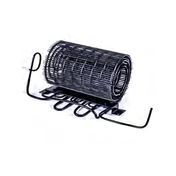 030 Multilayer Wire Tube Condenser for RefrigerationMultilayer wire tube condenser for refrigerators and freezers on R134a or CFC systems; electrophoresis-coated and available in folding, reel, or welded assemblies.View Product →
Build the first sample long, typically 10 to 15 percent above the calculated value, and trim in steps of 5 to 8 percent. Run each sample at steady state for at least 20 minutes at the design ambient, then record condenser outlet subcooling, evaporator outlet superheat, suction pressure, and pull-down time. A length change moves all four. A tube that looks correct on paper but leaves superheat below about 2 K is flooding the compressor, and the next step is more length, not more charge.
If the target superheat cannot be reached even with a deliberately long tube, the capillary is not the fault. Look at charge, condenser capacity, or airflow instead; the same diagnostics used in condenser maintenance and efficiency work here.
The short version: fix the bore from the choked-flow target, calculate the length from the required mass flow, rescale an existing tube only as a starting estimate, and finish the job with measured superheat and subcooling. Length is the last number you settle on, never the first.
Your email address will not be published. Required field are marked*

No.380 Kangyang Rd in the north,HuangdaiTown,Xiangcheng District,Suzhou City,215143

0512-65481378


