 English
 中文简体
中文简体Wholesale Refrigerator Condensers
HOME / PRODUCT


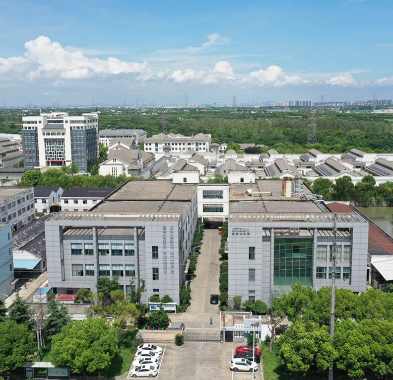
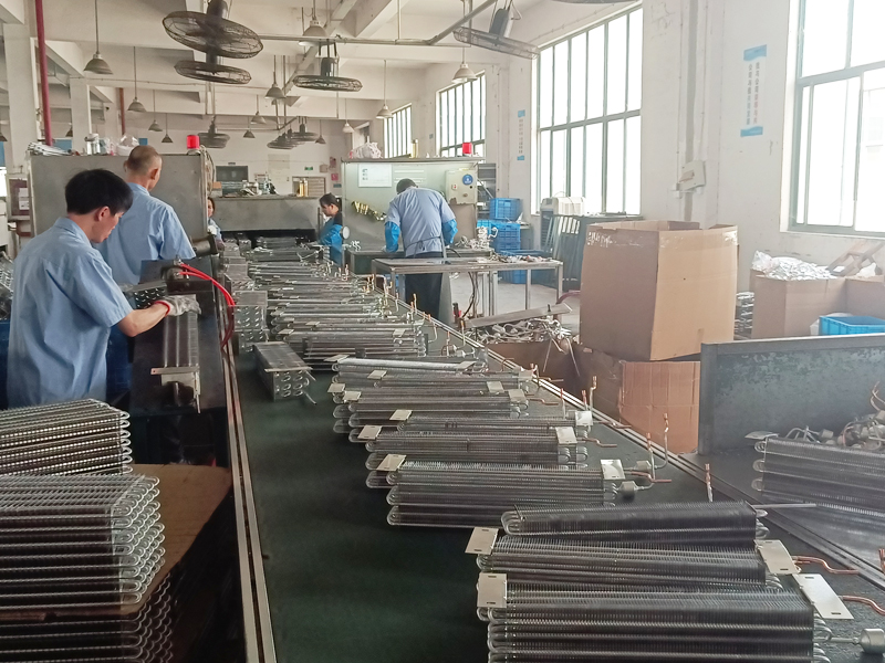
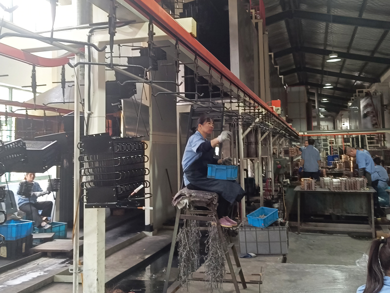
Suzhou Yikangda Electric Appliances Co., Ltd., was established in 1992 and specializes in the design, production and sales of home appliances condenser and evaporators for refrigerator, freezer, showcase, cold cabinet and water dispenser.
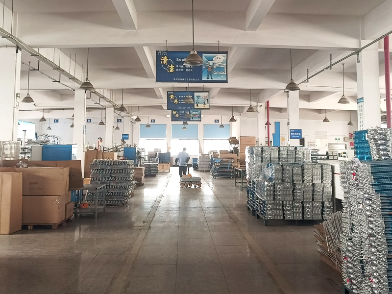
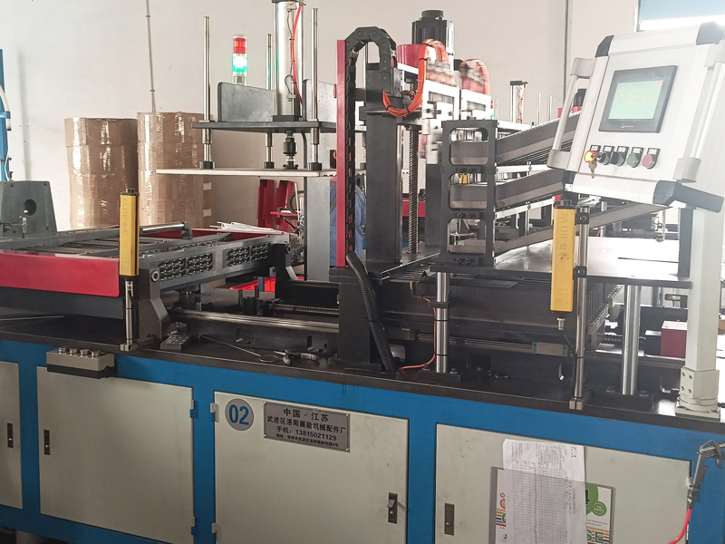
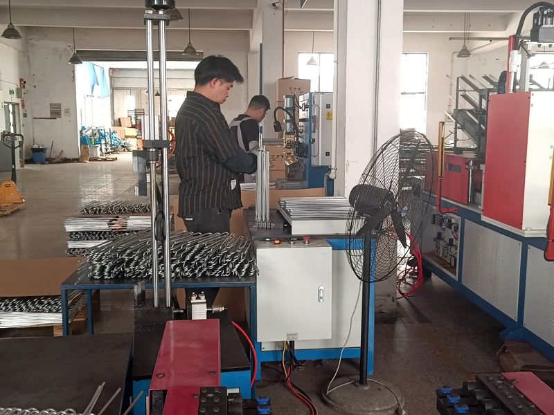
As Refrigerator Condensers Suppliers and Single Layer Wire on Tube Condensers Factory in China, our company occupies 10000m, including 16000m factory building, our company employee and technical management personnel own high quality and we own the advanced production and testing equipment. Depending on strong technique power and ability of developing new product, our products cover the whole domestic market and also exported to America, Europe, South East Asia, Middle East, South America North America, such as: United States,Italy, Korea,India Canada. We supply Wholesale Refrigerator Condensers and Evaporators. The quality and price are approved well by all customers.
The quality is the soul of one enterprise, we pass the certification of ISO9001 in 2001. From the selection of the raw material to quality test and after sales service, we execute strictly according too ISO9001 system, we have been imoroving steadily to make sure that offering the product with the quality and the competitive price to our customer.
We adhere to "make all effects to congregate top -Class talents, turn out products and promote itself to prestigious enterprise "as our idea for management strategy, We hope to work together,decelop together and usher in a better future together with all customers from home and abroad!
Built-in condensers deliver superior energy efficiency and space savings for modern HVAC systems by integrating the heat exchange unit directly into the main chassis, eliminating e...
View MoreWire Tube Evaporators Offer Proven Efficiency in Refrigeration Systems Wire tube evaporators are a robust and cost-effective heat exchanger design widely used in commercial refrig...
View MoreWire tube evaporators are a cost-effective and reliable heat exchange solution widely used in domestic refrigeration and light commercial cooling systems. Their simple structure, s...
View MoreIntroduction to Copper Tube Fin-Type Evaporators Copper tube fin-type evaporators are widely used in refrigeration and air conditioning systems due to their high thermal conductivi...
View MoreCorrect condenser-fan placement is one of the most cost-effective ways to improve system capacity. Place axial fans so their blades draw air uniformly across the coil face; staggered fan rows work best on large condensers to avoid localized recirculation. Keep a clear intake and discharge path: for outdoor units provide at least 1.5–2× coil depth of free space on the suction side and avoid nearby walls or obstructions that create swirl. When space is constrained, use ducting or turning vanes to straighten airflow, but accept the pressure drop in the selection of fan motor horsepower.
Fan type selection matters: axial fans are efficient at low to moderate pressure drops and are ideal for unobstructed outdoor condensers; blower/centrifugal fans are preferred when ducting, higher static pressure, or long discharge runs are necessary. For multi-fan banks, implement staggered start or soft-start controllers to avoid inrush-current issues and reduce vibration transmission to the coil header. Finally, measure actual face velocity with an anemometer during commissioning — target 2.5–3.5 m/s (500–700 fpm) for many tube-fin condensers as a starting point, then optimize based on refrigerant and ambient conditions.
Microchannel coils reduce refrigerant charge and weight and often provide lower air-side pressure drop for the same heat transfer area, but they are more sensitive to fouling and require careful brazing and handling to avoid cracking. Tube-fin (round-tube) coils are more tolerant of mechanical cleaning and localized repairs and allow easier header/access designs for brazing or tube replacement. Choose microchannel where space and charge reduction are priorities and where consistent, low-fouling air quality can be ensured; choose tube-fin for heavy-duty applications or where field repairability and aggressive cleaning are expected.
| Characteristic | Microchannel | Tube-fin |
|---|---|---|
| Refrigerant charge | Lower (often 30–60% less) | Higher |
| Repairability | Limited (panel-level replacement) | High (tube replacement possible) |
| Fouling sensitivity | High | Lower |
| Manufacturing complexity | High (precise brazing/extrusion) | Medium |
Fin density (FPI — fins per inch) should be matched to the air cleanliness and fan capability. Higher FPI increases heat-transfer area but raises air-side pressure drop and accelerates fouling in dusty or greasy environments. For open-air condenser coils in moderately clean locations, 10–14 FPI is often a practical compromise; for indoor or filtered systems you can consider 16–22 FPI if the fan can overcome the extra pressure drop. Louvering and louver angle change the local turbulence and heat transfer: shallow louver angles with staggered louver patterns improve moisture shedding and reduce frosting risk on refrigerator evaporators, while more aggressive louvering enhances heat transfer at the cost of higher pressure drop.
Controlling evaporator coil temperature to prevent ice while maximizing capacity requires coordinated superheat control and defrost strategy. Maintain measured superheat at the outlet recommended for the refrigerant and load type — commonly 6–12 K (10–20 °F) for many systems — by adjusting the thermostatic expansion valve (TXV) or electronic expansion valve (EEV). For systems prone to frosting (high humidity, low load), favor frequent short defrost cycles rather than long infrequent ones; short electric or gas defrosts reduce energy penalty and limit melt-water carryover. Consider demand defrost logic (defrost only when suction temperature and runtime indicate frost) to minimize unnecessary defrosts.
When retrofitting defrost methods, evaluate hot-gas defrost for systems with available high-pressure refrigerant taps — it provides rapid coil thaw but requires careful check-valving to prevent migration. For food applications, ensure drain pans and slope facilitate meltwater removal and that defrost controls are interlocked with fans when necessary to prevent cold-air recirculation during defrost.
A maintenance-first design extends coil life and maintains capacity. Establish inspection intervals based on environment: urban/industrial locations inspect monthly for grease and particulate; rural/clean locations can inspect quarterly. Use soft brushes, low-pressure power washing (max 30–50 bar depending on coil spec) and chemical cleaners only when compatible with fin material and manufacturer guidance. Avoid high-pressure, direct-stream washing on microchannel or thin-aluminum fins — damage is cumulative and often invisible until leaks occur.
| Task | Frequency (typical) | Key check/metric |
|---|---|---|
| Visual coil/fin inspection | Monthly to quarterly | Blocked fins, corrosion, grease |
| Airflow measurement and fan balance | Annually or after repairs | Face velocity, static pressure |
| Chemical clean (where allowed) | 6–24 months (depends on fouling) | dP across coil, temperature split |
Material pairing and joining technique are critical. Copper tube/aluminum fin combinations remain widely used because of thermal performance and repairability; aluminum microchannel often uses aluminum-to-aluminum brazing or specialized welding and requires compatible filler alloys. For mixed-metal joins, beware of galvanic corrosion — design for sacrificial anodes or coatings in corrosive atmospheres. Use silver-based brazing alloys for copper refrigeration joints where high strength and corrosion resistance are required; ensure flux compatibility and proper joint clearance (typically 0.05–0.2 mm) for capillary action. Vacuum brazing for aluminum assemblies reduces oxidation and improves joint integrity for microchannel panels.
Condenser performance is highly sensitive to refrigerant charge and degree of subcooling. Undercharge reduces subcooling and lowers condenser heat rejection capacity; overcharge can flood the condenser and raise head pressures. Target subcooling depends on system design but often sits between 5–12 K (9–22 °F) for many HFC/HCFC systems; tighter subcooling (higher values) indicates more effective condenser heat rejection but can point to overcharge or excessive liquid receiver volume. During commissioning, measure liquid-line temperature and compare to saturation temperature calculated from high-side pressure; each 1 K of subcooling corresponds roughly to a 1% improvement in refrigeration effect in many cycles, but the exact figure depends on evaporator and compressor specifics.
| Symptom | Likely cause(s) | Quick check |
|---|---|---|
| High head pressure | Dirty condenser, insufficient airflow, overcharge, noncondensable gas | Check fan operation, measure condenser dP and subcooling, purge noncondensables |
| Low suction pressure | Insufficient refrigerant, TXV stuck, evaporator airflow low | Measure evaporator superheat, inspect TXV sensing bulb and air filters |
| Excessive liquid-line temperature | Low subcooling, overcompressing, heat pickup in liquid line | Measure line temps, check for proper receiver and subcooler function |

No.380 Kangyang Rd in the north,HuangdaiTown,Xiangcheng District,Suzhou City,215143

0512-65481378


